Rust Embedded: Blinky - Part 1
We are going to start off with the “Hello World” of embedded progamming - blinking an LED. And we are going to do this as raw as possible. By raw i mean, that for now we are not going to use any HAL crate. HAL stands for “Hardware Abstraction Layer”. There a few different HALs for different Microcontrollers. Basically these crates provide standardized APIs for interacting with the Microcontroller and its peripherals.
Code on GitHub.
Here is the full code example for our raw blinky program. Further down we’ll go through the code in more detail.
#![no_main]
#![no_std]

extern crate panic_halt;

use core::{
    arch::asm,
    ptr::{self},
};

use cortex_m_rt::entry;
use cortex_m_semihosting::{self, hprintln};

const RCC: u32 = 0x4002_1000;
const RCC_CR: *mut u32 = (RCC + 0x00) as *mut u32;
const RCC_AHBENR: *mut u32 = (RCC + 0x14) as *mut u32;

const GPIOE: u32 = 0x4800_1000;
const GPIOE_MODER: *mut u32 = (GPIOE + 0x00) as *mut u32;
const GPIOE_ODR: *mut u32 = (GPIOE + 0x14) as *mut u32;
const GPIOE_BSRR: *mut u32 = (GPIOE + 0x18) as *mut u32;

#[entry]
fn main() -> ! {
    // You should see that in your openocd output
    hprintln!("Hello from Discovery");

    unsafe {
        let mut val = ptr::read_volatile(RCC_CR);
        // Use the HSI as system clock (8MHz)
        val |= 1 << 1;
        ptr::write_volatile(RCC_CR, val);

        val = ptr::read_volatile(RCC_AHBENR);
        // Enable GPIO E clock
        val |= 1 << 21;
        ptr::write_volatile(RCC_AHBENR, val);

        // Set Pin 9 to output: PE 9 = Bit 19 & 18
        val = ptr::read_volatile(GPIOE_MODER);
        val &= 0xFFF3_FFFF; // Clear Bit 19 & 18
        val |= 1 << 18; // Set Bit 18
        ptr::write_volatile(GPIOE_MODER, val);

        loop {
            // Read in the output data register of GPIO Port E
            let val = ptr::read_volatile(GPIOE_ODR);
            // If Pin 9 is currently in High state, switch to Low,
            // otherwise switch to High
            if val & (1 << 9) == (1 << 9) {
                // Set Pin 18 Low
                ptr::write_volatile(GPIOE_BSRR, 1 << 25);
            } else {
                // Set Pin 18 High
                ptr::write_volatile(GPIOE_BSRR, 1 << 9);
            }

            delay();
        }
    }
}

unsafe fn delay() {
    // Delay for approx 1s - found 80.000 by "brute force"
    for _ in 0..80_000 {
        asm!("nop");
    }
}
The first 2 lines are important. Because we do not have an operating system, like Linux or Windows, running on our embedded device, we cannot use the rust std library. That’s why we need the #![no_std]. The #![no_main] is needed because we are going to annotate our main function with the entry attribute from the cortex-m-rt crate and by that, we create our own custom main function. At the beginning I mentioned, that we are going to do it raw. And now I am writing about a cortex-m-rt crate. This is, because I tried to be as raw as possible. This crate however is needed because it does the heavy lifting at the beginning of our program (initialising the microcontroller etc.). The rt basically stands for runtime.
Next we need another crate - the panic-halt crate. Every embedded programm needs a handler for panics, and this crate provides exactly that.
const RCC: u32 = 0x4002_1000;
const RCC_CR: *mut u32 = (RCC + 0x00) as *mut u32;
const RCC_AHBENR: *mut u32 = (RCC + 0x14) as *mut u32;

const GPIOE: u32 = 0x4800_1000;
const GPIOE_MODER: *mut u32 = (GPIOE + 0x00) as *mut u32;
const GPIOE_ODR: *mut u32 = (GPIOE + 0x14) as *mut u32;
const GPIOE_BSRR: *mut u32 = (GPIOE + 0x18) as *mut u32;
First we define some constant pointers to registers we later need. First the RCC register - reset and clock control. You can find the base address of the RCC registers in the reference manual of the STM32F303 microcontroller beginning at section 3.2.2 - Memory map and register boundary addresses on page 54.
 STM32F3 Reference Manual p. 54
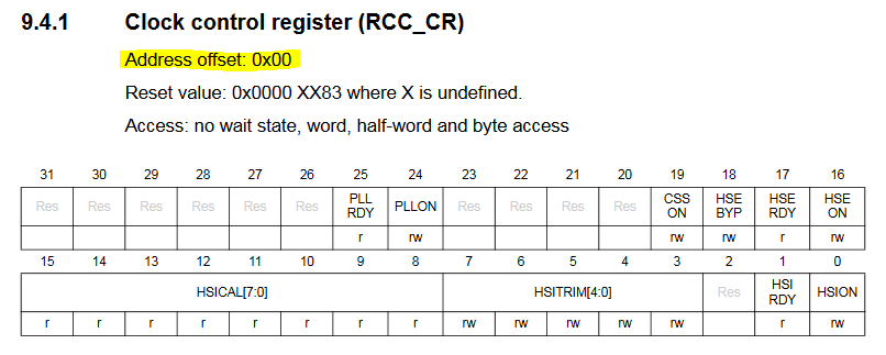
The offsets for the RCC_CR (control register) and RCC_AHBENR (AHB peripheral clock enable register) can be found under section 9.4.1 - Clock control register on page 139 and under section 9.4.6 - AHB peripheral clock enable register on page 151 respectively. The responsibilities of each bit are also detailed at each section.
 STM32F3 Reference Manual p. 139
Next we need some pointers for our output port - we use port E. To be able to configure, read and write to port E, we need the base address, the address for the port mode register, the output data register and the port bit set/reset register. Again, you find the base register in section 3.2.2 and the offsets for each register in their respective sections starting from section 11.4 GPIO registers.
On to the actual implementation.
#[entry]
fn main() -> ! {
    // You should see that in your openocd output
    hprintln!("Hello from Discovery");

    unsafe {
        // code...
    }
}
As mentioned in the first paragraph, we need to annotate our main function with the entry attribute. The hrprintln!() is not really needed here, I inserted that for debugging reasons. After that comes the not so nice part - we need to wrap our code into an unsafe section, which is what you actually don’t want to use in a Rust project. But because we are doing it raw we have to use it.
let mut val = ptr::read_volatile(RCC_CR);
// Use the HSI as system clock (8MHz)
val |= 1 << 1;
ptr::write_volatile(RCC_CR, val);

val = ptr::read_volatile(RCC_AHBENR);
// Enable GPIO E clock
val |= 1 << 21;
ptr::write_volatile(RCC_AHBENR, val);

// Set Pin 9 to output: PE 9 = Bit 19 & 18
val = ptr::read_volatile(GPIOE_MODER);
val &= 0xFFF3_FFFF; // Clear Bit 19 & 18
val |= 1 << 18; // Set Bit 18
ptr::write_volatile(GPIOE_MODER, val);
In the first part we are initializing port E. First we the define, that the HSI (high speed internal clock) clock should be used as the system clock which runs at 8 MHz. Next we write 1 into bit 21 of the AHB peripheral clock enable register to enable the GPIO E clock. Lastly we need to set pin 9 of port E as output. Therefore we set bit 18 of the GPIOE mode register to 1. Now we are setup to make our LED blink by setting pin 9 to high and low in a loop.
loop {
    // Read in the output data register of GPIO Port E
    let val = ptr::read_volatile(GPIOE_ODR);
    // If Pin 9 is currently in High state, switch to Low,
    // otherwise switch to High
    if val & (1 << 9) == (1 << 9) {
        // Set Pin 18 Low
        ptr::write_volatile(GPIOE_BSRR, 1 << 25);
    } else {
        // Set Pin 18 High
        ptr::write_volatile(GPIOE_BSRR, 1 << 9);
    }

    delay();
}
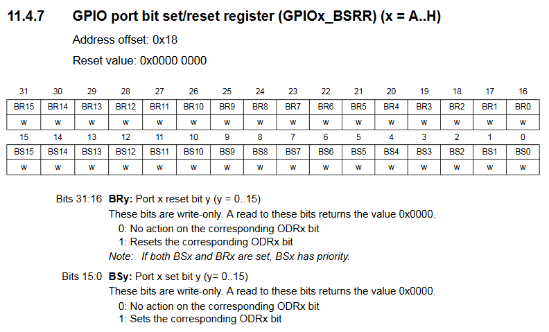
In the loop, we first read the current state of port E from the GPIOE output register. In the if statement we check, if pin 9 of port E is currently set to 1 (high). If so, we write 1 into bit 25 of the GPIOE port bit set/reset register. Bits 16 to 31 of this register map to the corresponding bit in the output data register. And by writing a 1 into those bits, we can reset the bit in the ODR. Respectively we can set bits 0 to 15 which would set the corresponding bit in the ODR. So to set pin 9 to low, we need to write 1 into pin 25 (BR9) of the BSRR, and to set pin 9 to high, we need to write 1 into bit 9 (BS9).
 STM32F3 Reference Manual p. 240
Last we insert a delay of about 1s before we start the loop again.
Maybe you are asking yourself why we use this ptr::read_volatile and ptr::write_volatile functions to set and read bits from registers. Those functions guarantee that the compiler is not optimizing away instructions, and that we always really read and write the bits of the registers.
On to Part 2 -> Rust Embedded: Blinky - Part 2